
Tomei
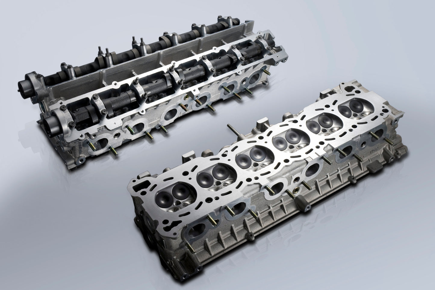
Complete Cylinder Head RB26, R32-R34
Complete Cylinder Head RB26, R32-R34
Regular price
$7,200.00
Regular price
$8,500.00
Sale price
$7,200.00
Unit price
per
Shipping calculated at checkout.
Couldn't load pickup availability
High RPM and high output. The parts and head tuning that are essential to achieve these goals!
NOTE: This is a special order item, please contact us at sales@legendofr.com before purchasing.
PRODUCT INFO
| APPLICATION | TYPE | PART | P/N | NOTE | |
|---|---|---|---|---|---|
| RB26DETT | BNR32 BCNR33 BNR34 |
With out camshaft | CPH-RB26 | 231012 | |
| BNR32 BCNR33 |
With camshaft | CPH-RB26R32-C | 231112 | ||
| BNR34 | CPH-RB26R34-C | 231122 | |||
FEATURE / SPEC
| TYPE | With out camshaft | With camshaft |
|---|---|---|
| P/N | 231012 | 231112/231122 |
| BASE ENGINE | ||
| COMBUATION CHAMBER VOLUME | ||
| VALVE | ||
| VALVE SPRING | ||
| VALVE SPRING RETAINER | ||
| CONNECTING ROD | ||
| VALVE GUIDE | ||
| VALVE SHEET RING | ||
| CAM SHAFT | TOMEI IN/EX 270-10.25 | |
| VALVE LIFTER | TOMEI High Strength Chrome-Moly Steel + Cold Forging, for High Lift Camshafts | |
1:VALVE GUIDE REPLACEMENT
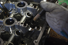 |
The cylinder head is heated up 200℃ so that the stock valve guides can be removed. The cylinder heads that are made from aluminum alloy when heated expands more than the materials that the valve guides are made from thus making it easy to remove when heated. The TOMEI Valve guides are also inserted in the same way but the Valve Guides are frozen in liquid nitrogen with to bring down the valve guides temperatures to -200℃ and with 400℃ difference it is then made possible to insert the new Valve guides into the Cylinder Head with ease and safely. If liquid nitrogen is not used then damage can be caused during the removal and re-installation of the valve guides as the gap will not be wide enough to fit the new valve guides into the head. This can also cause the deformation of the valve and create gaps which can lead to oil leaks. |
2:VALVE SEAT RING INTERNAL DIAMETER ENLARGEMENT
 |
The inner diameter of the valve seat ring is enlarged to accommodate for the oversized valve. There is much more involved than just simply enlarging the valve size and the ring seats. Much consideration in redesigning and experience is vital so not to risk weakening the structure and or hindering performance. It us also involved to the aerodynamics of the intake and exhausts ports with all angles and flow dynamics taken into consideration. |
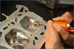
3:VALVE SEAT CUT
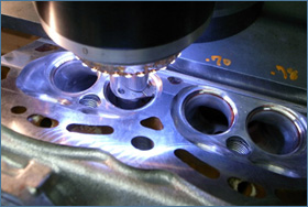 |
Each valves seat width,position,taper angle and the surface condition is addressed to maximize the aerodynamics of the mouth from the ports & valve to the combustion chamber and back to the exhaust port. Each seat is cut to suit each valves position,tapered angle with all surface angles arranged to optimize port flow to the valve and to the combustion camber. By increasing the sealing properties of the valve to the valve seat than more accurate compression can be maintained from preventing any pressure from escaping through any gaps. This process is extremely time consuming to find the optimum design and setup to suit each engine with each engines design characteristics and to suit the engines purpose. |
4:OPTIMIZING THE COMBUSTION CHAMBER
 |
The valve seat rings surrounding area may have some imperfections which also affects the combustion chambers volume as it was designed from factory. So by targeting this area the flow can be optimized which will also reduce any signs of flow disruptions. The multivalve engine designs which tend to have a limited area and the combustion chamber walls can cause resistance and limitations. A vital process is to deburr any casting imperfections on the port area just above the seat ring. These factory casting imperfections hinders the air flow to the combustion chamber which restricts performance. Smoothing this area is an absolute must and extra care and attention is taken into account for the airflow and dynamics of this area. |
5:PORT STEP CORRECTION
 |
Correcting the valve sheet rings helps optimize the combustion chamber shape and makes the flow characteristics much better on the Intake and Exhaust side. |
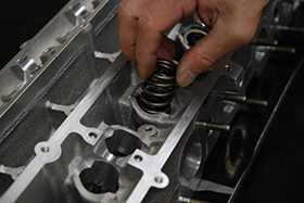
6:VALVE SPRING SET ADJUSTMENTS
 |
The valve springs will need to be upgraded to help keep a good balance for low and high engine speeds. The added weight reduction will help the valve train assembly. The key points are the set load properties of the valve spring and also the weight reduction. Checking the valve length extension to measure the valve sheet cut,and then setting the valve length through the set of valve spring sheet adjustments. This process will show the valve springs design efficiency which also means that the load is then set. |
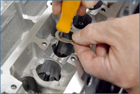
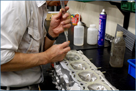
7:VALVE FRICTION ADJUSTMENTS
 |
Lapping compound is then used to lap the valve and seat ring to check for correct sealing and contact areas of the valve to the seat ring. The right contact area amount is then identified and the correct adjustments can then be made to optimize seal and prevent any gas leaks. If the contact area us too large then there is a risk of collecting grit and grime or developing a buildup of carbon which can damage both the valve and seat ring and loose performance. If the contact area is too narrow then the force loads on the seat ring is too high and the valve will not be able to cool down efficiently as the heat cannot dissipate to the cylinder head effectively. Lapping must be done with care and with detailed attention so as not to damage the prepared seat ring and valve surface. |
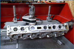
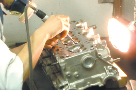
8:HEAD SURFACE CORRECTION
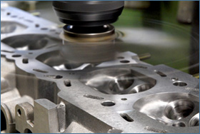 |
The head is checked for any signs of deformation and then corrected with the mill cutter to make the appropriate corrections. This will increase the heads plane to improve sealing characteristics with a secure flat face to met will to the cylinder block. Having corrected the face of the head will help increase compression and give more power. |
9:WASHING
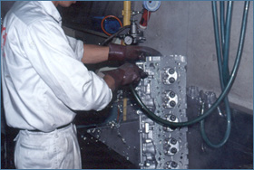 |
Complete cleaning of the water & oil lines is meticulously done by hand manually with each and every block with every orifice and areas checked thoroughly, Then finished off with a high pressure hot wash in a specialized machine and finally completed with a high pressure air clean in every line, gaps and orifices. This extensive 3 stage process is time consuming but an absolute must to completely eradicate any unwanted burr and foreign material from causing harm to the internals. |
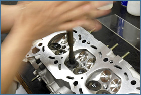
10:COMBUSTION CHAMBER CAPACITY ADJUSTMENTS
 |
Larger valve seats rings are fitted and adjusted,the valve seats are then cut and finally the combustion chambers are carefully calculated and adjusted to suit the target displacement on each cylinder. The engines have their cylinder compression chamber rations all adjusted to suit the target volume. Meticulous attention to detail and precision adjustments of 0.0-0.9cc is normal in our standards to attain the optimum smooth. |
11:PRECISION ASSEMBLY
 |
Our precision assemblies are well known throughout the years and have been our trademark. Our high standard of work has proven records on the street, track and evens to deliver results when needed most. Our stringent levels of operations management in materials and processes reflect on our products performance throughout the years. |